I tried to document all the major steps I put into building my 2176 motor, hopefully some of it will be useful to someone...
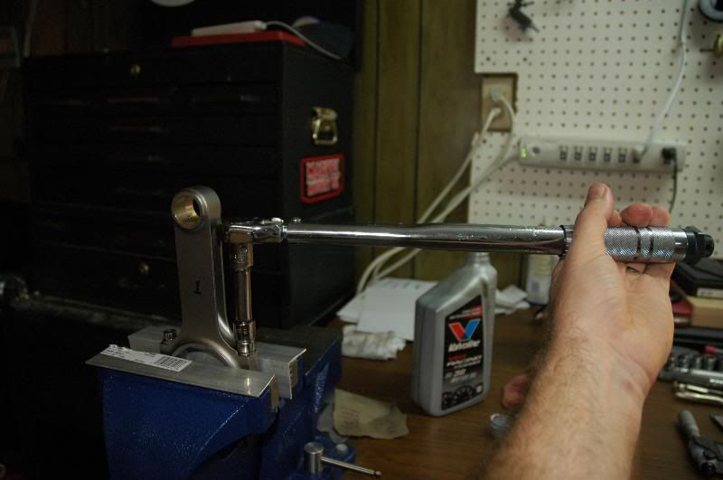
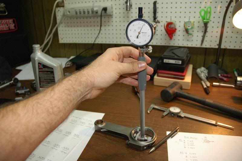
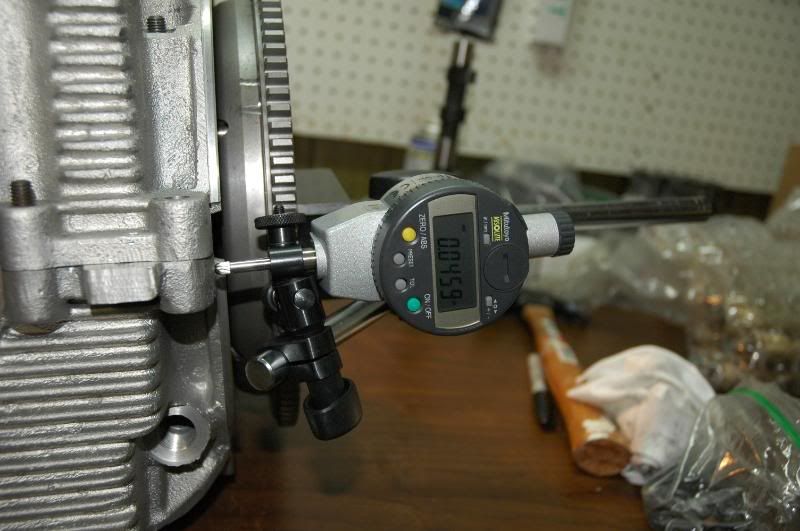
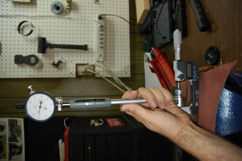
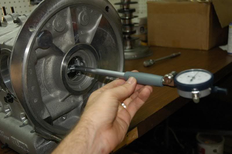
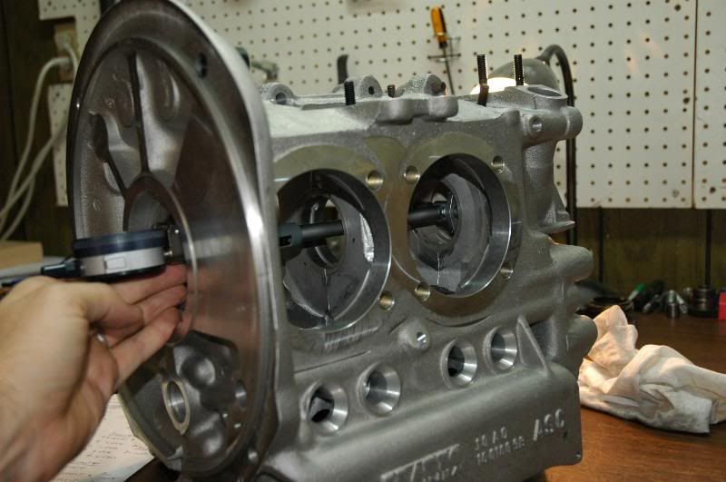
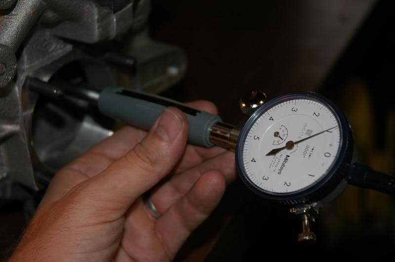
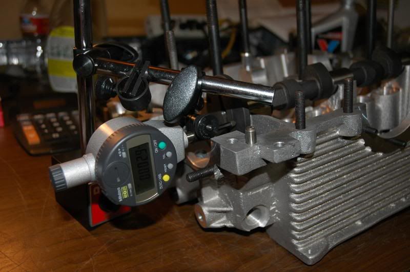
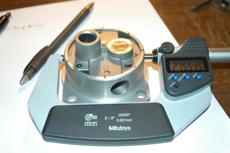
One of the first things to do is to check main bearing clearances. Don't assume that just because you were told your main crank journals were such-and-such a size (say .010" smaller than std) and that you bought the right bearings that your oil clearances are going to be right. In my case, I had to buy a second set of bearings (Kolbemschmidts, the good stuff) to get a #4 bearing I was satisfied with and I had to do a little work to the #2 bearing saddle on the case to get that bearing right. I was aiming for .0025-.003" radial oil clearances on all the mains. In the end they were all about dead on, but if I had just slapped it together w/o checking things I would have had really tight #'s 2 and 4 bearings, which could have seized. The most accurate way to determine oil clearances is with the use of a properly calibrated dial bore indicator for the bearings and a micrometer for the journals. If you use the same micrometer to calibrate the bore indicator that you use to measure the journals your numbers should be accurate. The journals are self explanatory, and I measure each every 45 degrees and record those numbers. They will not be "perfectly" round, so you want to know what the max and mins are for each journal. For the bearings, you want to put all 4 main bearings in the case and torque the case halves together so you have the proper bearing crush. Make sure everything is absolutely SPOTLESS when you are assembling it, a tiny piece of dirt between the saddle and bearing can really throw off the readings. I also measure each bearing every 45 degrees and write down all these measurements. So here's what measuring the main bearings looks like:
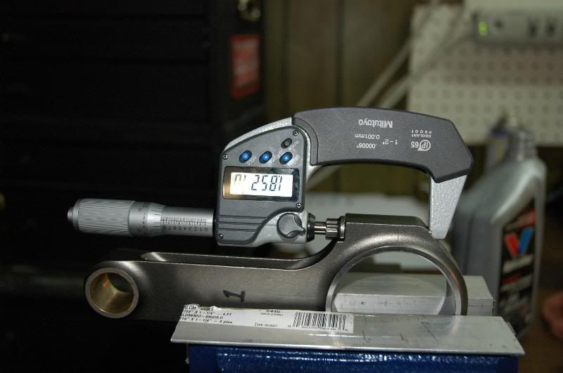
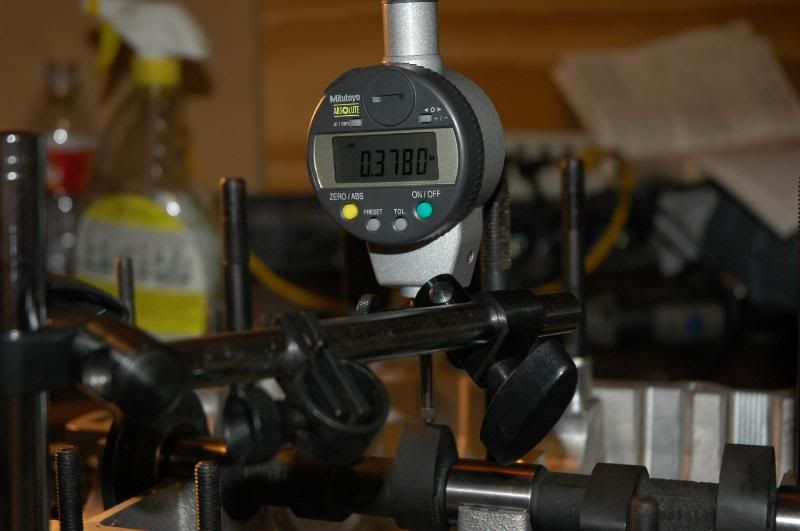
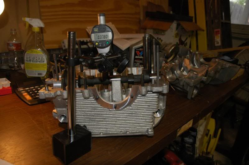
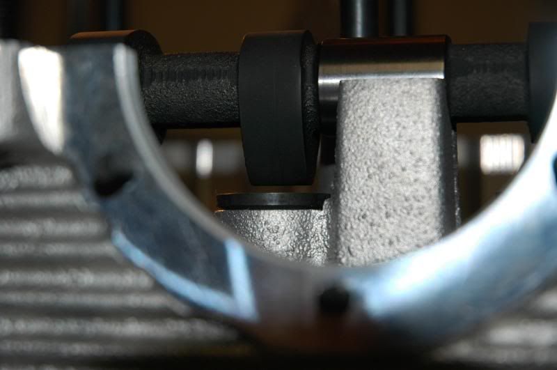
Calibrating the dial bore indicator:
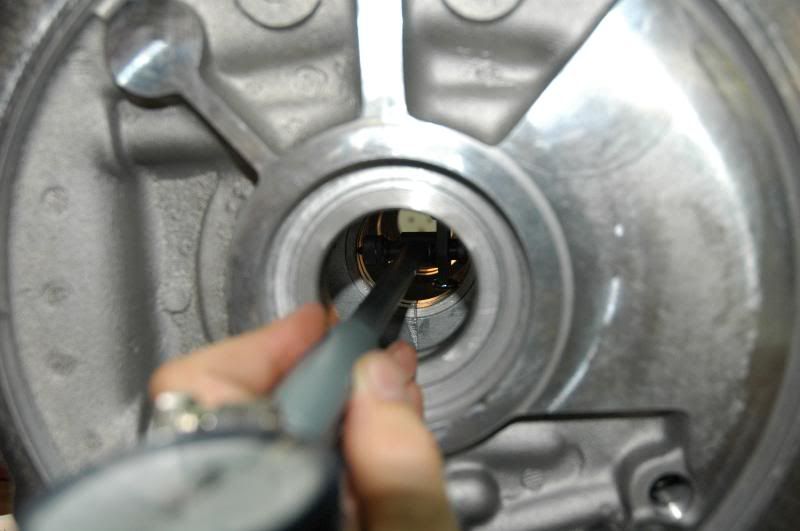
Measuring bearing #1
Main bearing #2
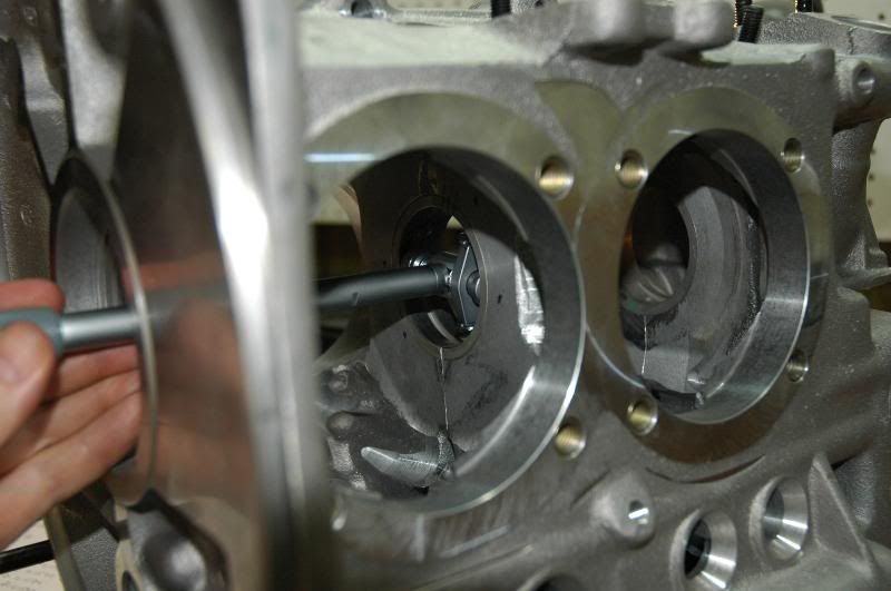
Main bearing #3
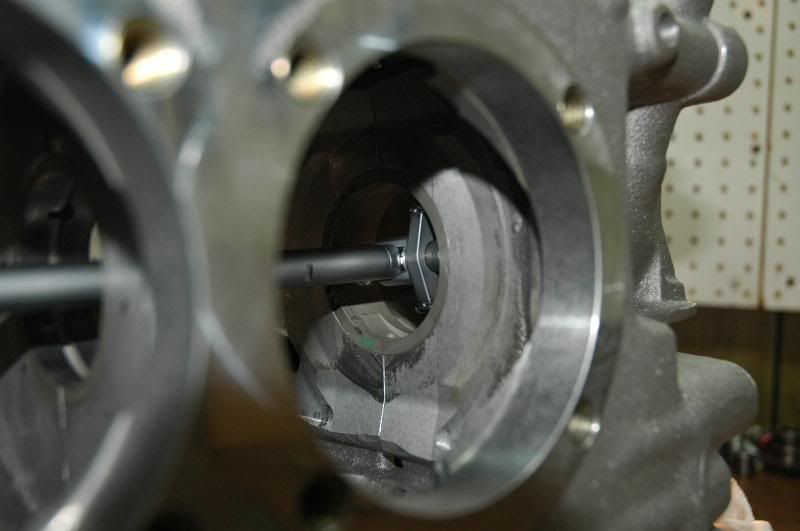
Main bearing #4
Once you have all journal and bearing measurements written down, compare the pairs to find the minimum, maximum, and average oil clearance for each journal/bearing set and make sure they are within your desired tolerances.
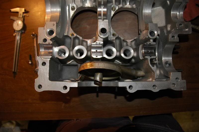
The next thing I do is to check how well the oil grooves or holes in the bearings line up with the oil galleys in the case. You'd think they would line up nicely, but it is not uncommon for them to be pretty far off. If they are off far enough it could limit oil flow to that bearing, not a good thing. So I check each bearing mad make sure there is good alignment and modify the bearings as necessary.
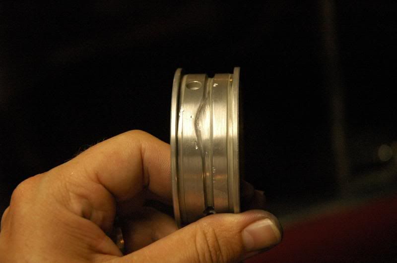
First I measured the location of the oil galley for the #1 bearing and marked it on the bearing, along with an area to blend it in with the original groove. You can see from where it's marked that about half of the oil galley was blocked by the bearing
The #2 bearing was about 1/3 blocked, not too bad...
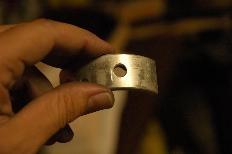
The #1 bearing with modified oil groove
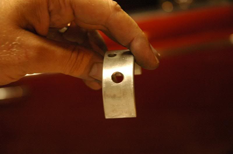
The #3 bearing needed about the same amount of midification
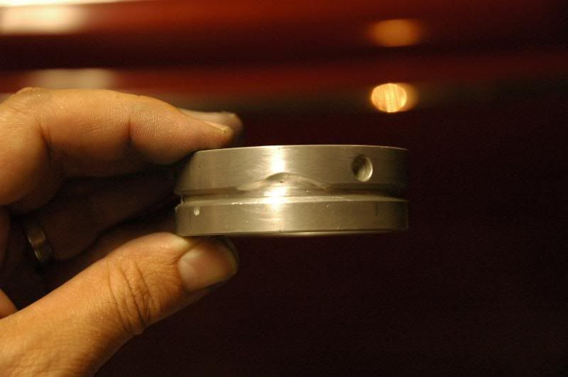
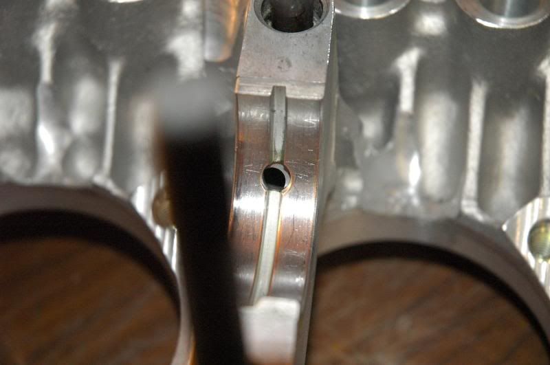
Scribe lines on the #2 bearing locating the oil galley
Its hard to see in the picture, but the bearing hole on the saddle side of the bearing is stretched to meet the oil galley hole in the case
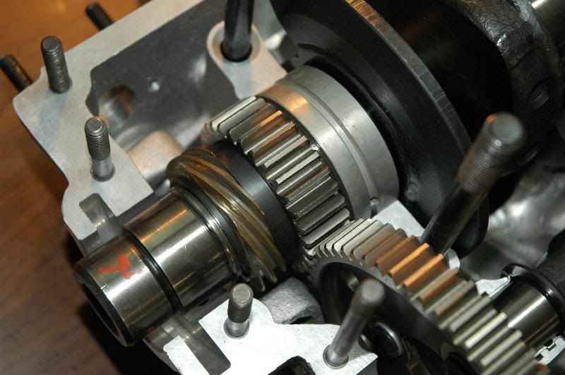
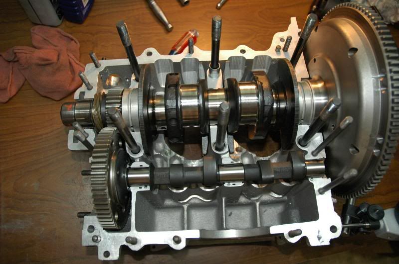
Next comes the cam. Basically I do this the same way I do the main bearings and journals, although it's obviously a lot less critical, It's still good to make sure everything is within tolerance
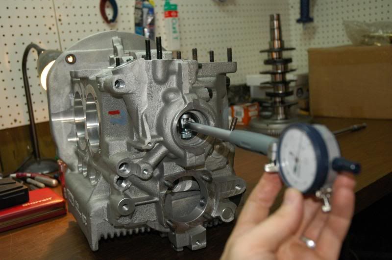
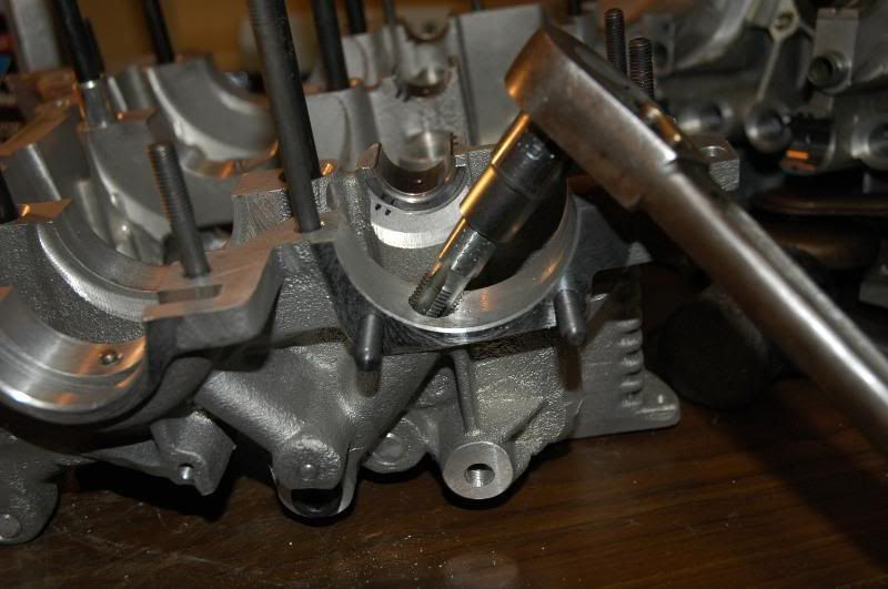
Measuring cam bearings with the dial bore indicator, I do this with the main bearings in the case and the case torqued down to spec. Same procedure as the main bearings, 4 measurements per journal and bearing, then compare...
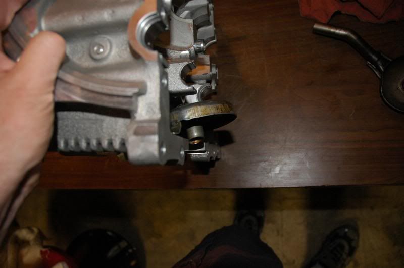
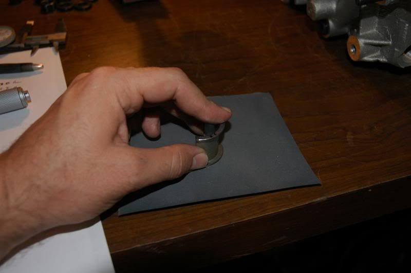
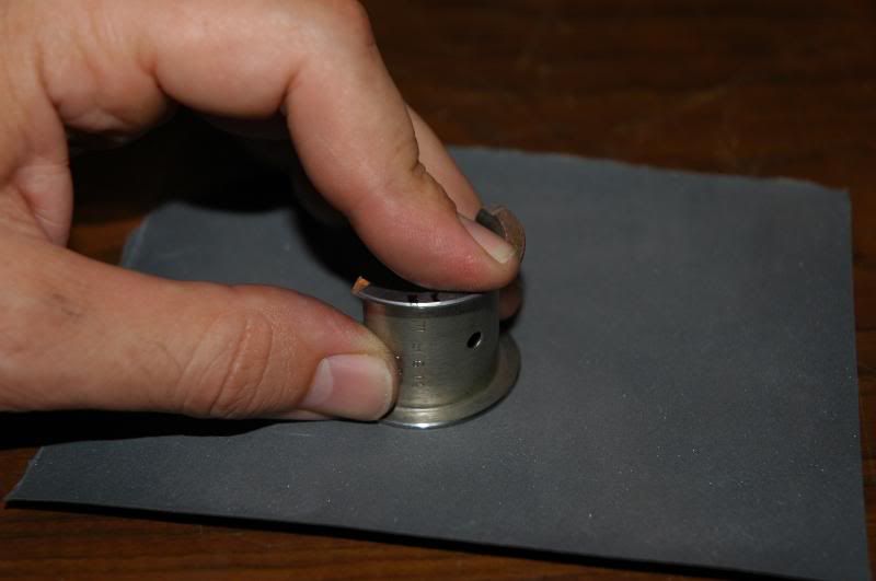
The thrust bearing is basically too long as it comes so you have to modify it to achieve the proper thrust clearance for your particular cam. Only do this on one thrust surface of each half of the thrust bearing, and make sure it is the same side of both. Basically just try to apply even pressure on some medium grit emery paper, I like to take measurements pretty often to make sure I am taking material off evenly, and that both halves end up the same. You can measure your cam and then subtract your target thrust form that number to determine the size you need to make the bearings...
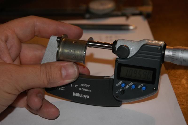
Checking cam thrust. I set it at about .003"
This is a good time to check total lift at the cam....
Also check cam to lifter clearance, I wouldn't want less than about .060" or so...
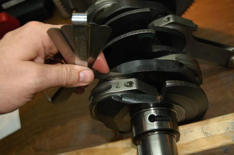
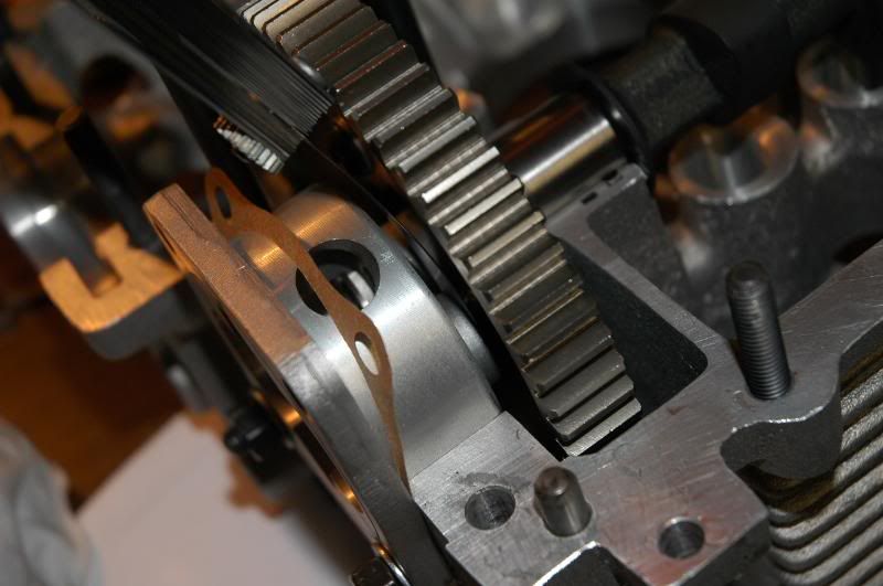
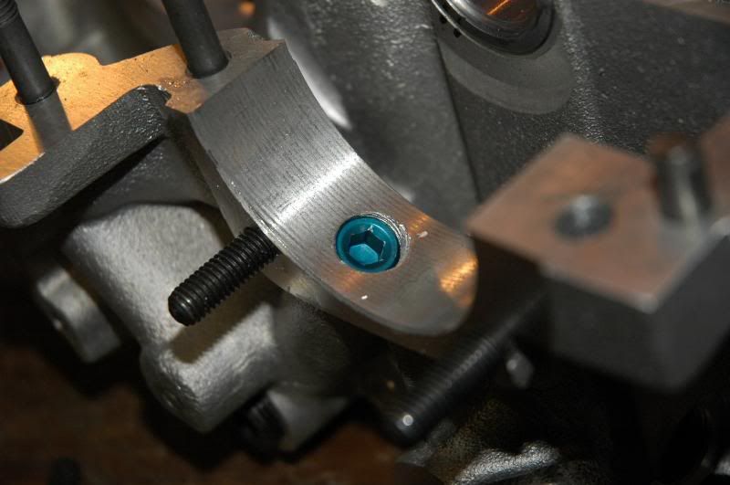
This is probably a good time to check for cam gear bolt to oil pump clearance. You may need to grind you cam bolts or oil pump housing a bit, in my case I had to grind the pump housing a little to get enough clearance. I think to start with I had like .016" clearance, and I ground the pump till I had like .040-.050", which should be plenty...
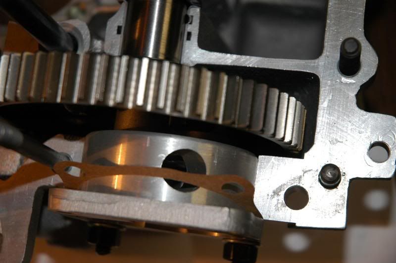
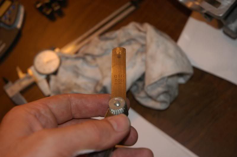
Measuring clearance with a feeler gauge...
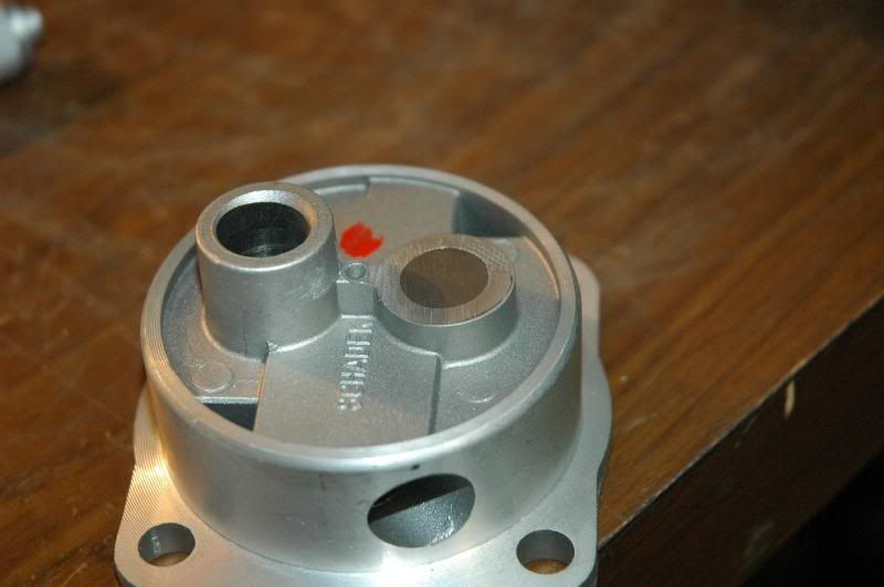
You can see here when I did some grinding on the pump body...
I also blueprinted the oil pump into the case. Same basic procedure as bearings, torque down the the case, measure every 45 degrees, and measure the pump every 45 degrees. Compare corresponding diameters, you want a nice tight fit with out too much slop, but you also don't want it to be impossible to get the pump in the case. about half to one thousandth should be fine...
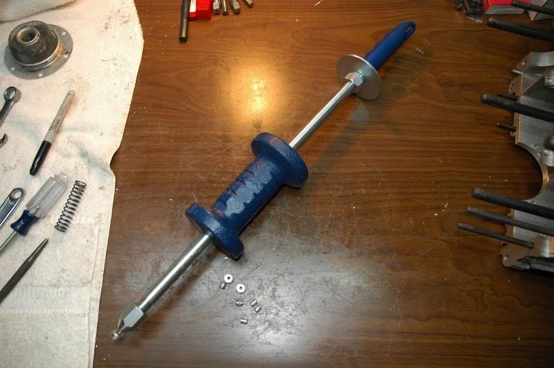
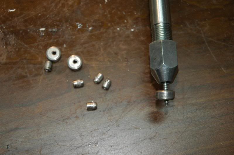
One of the next things I did was to pull the case plugs out and replace them with pipe plugs. The advantage of this is that you can *really* clean all the oil galleys in the case. There's just no way to really get all the crap out of them without having the plugs removed. There will be metal shavings that collect in the oil galleys from any machining you had done on your case if its a new case, and if its a used case, well, who knows what lurks inside there. Better to open it up and and then *know* theyre clean. Easiest way to get the aluminum plugs out is with a slide hammer with a sheet metal screw on the end. Drill a hole in each plug, thread the screw into it, attach it to the slide hammer, then give it a good tug, it will come right out...
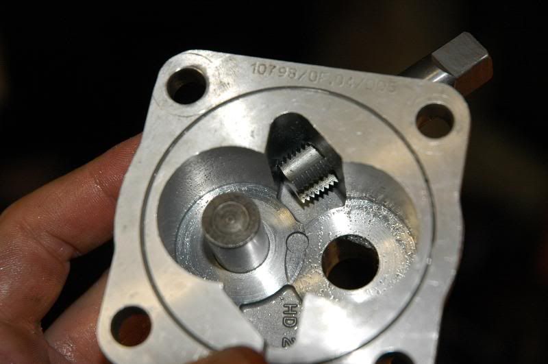
Drill and tap the holes with the appropriate drills and taps (I'll look up the sizes later and add them)
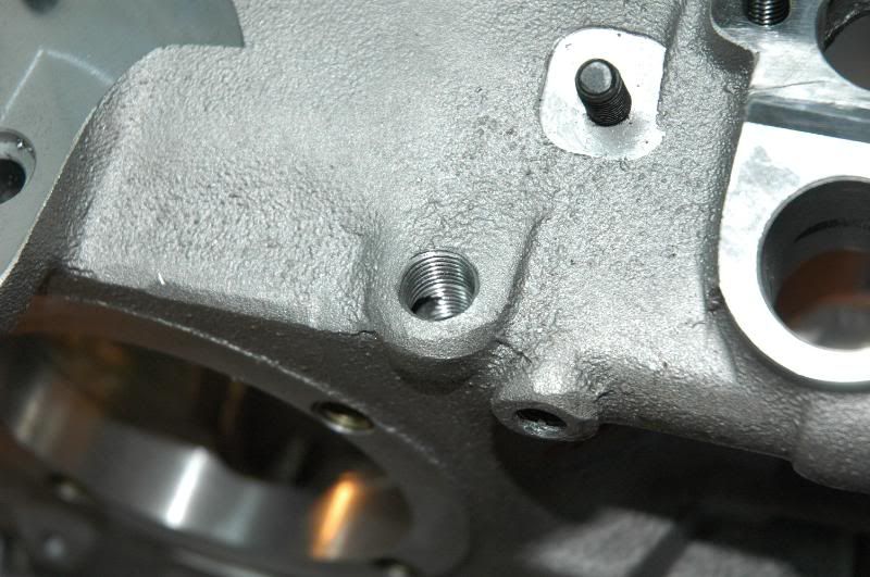
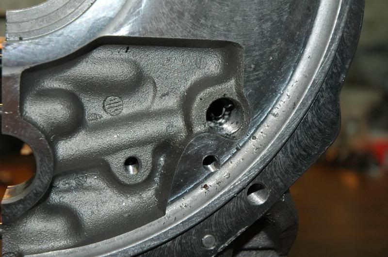
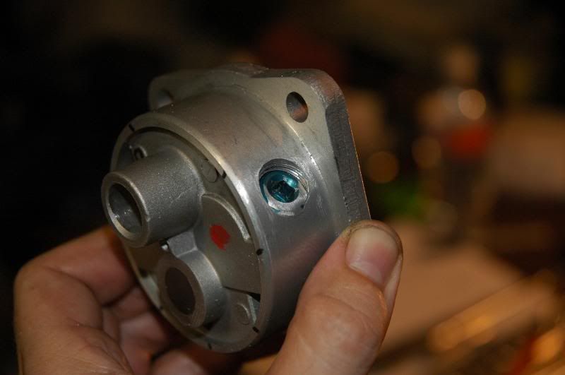
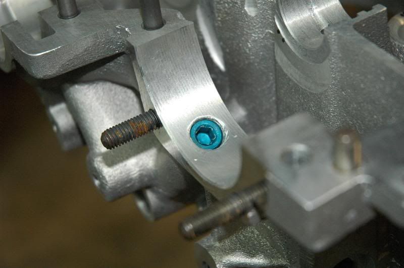
For full flow applications you want to tap and plug the oil inlet on the case from the pump and the oil outlet of the pump.
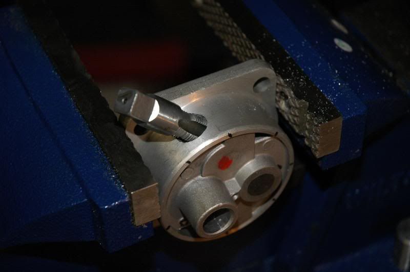
Depending on the tap you use, you may not be able to go deep enough on the pump body for the plug to be sunk in far enough. No big deal, just grind the outside of the plug as needed...
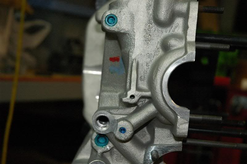
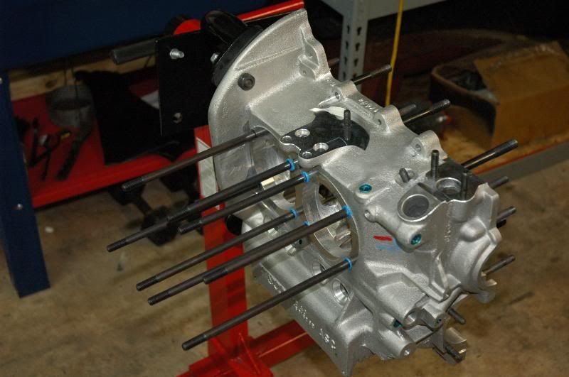
The case with all the plugs installed. Use a teflon automotive thread sealant to seal these, I found out the hard way that Curl-T does not make a good thread sealant...
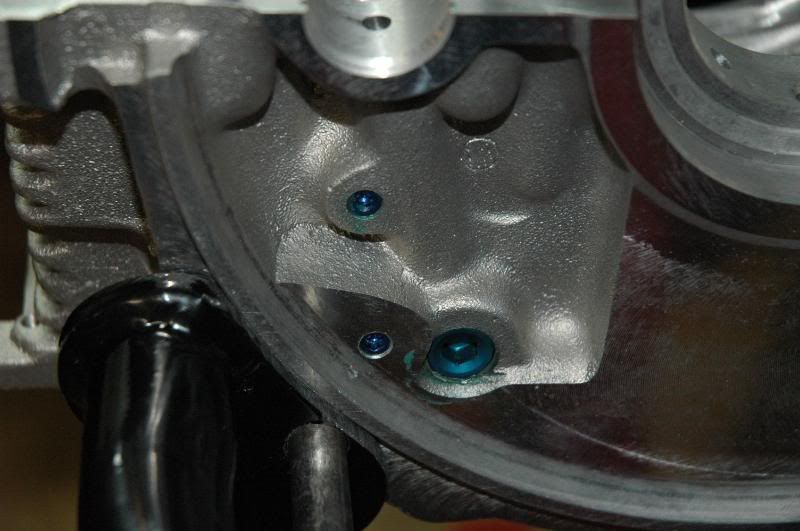
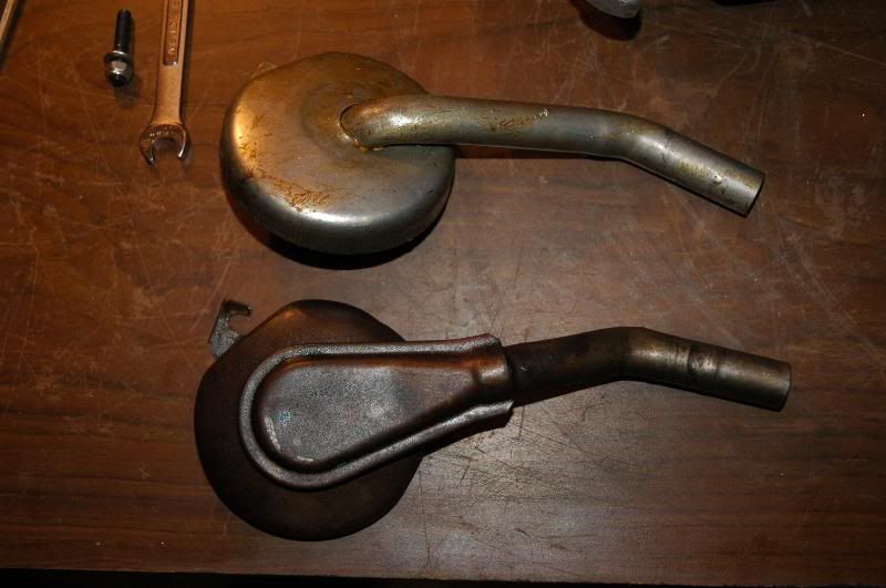
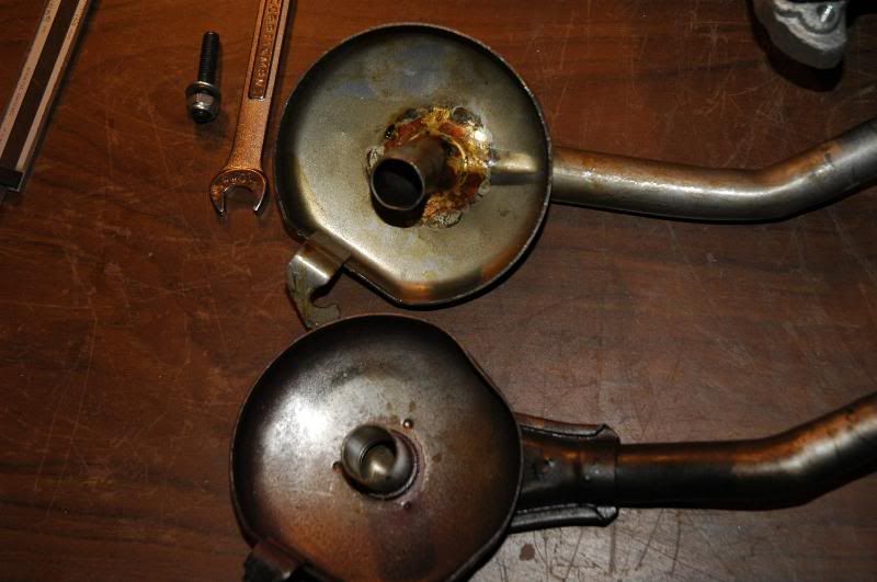
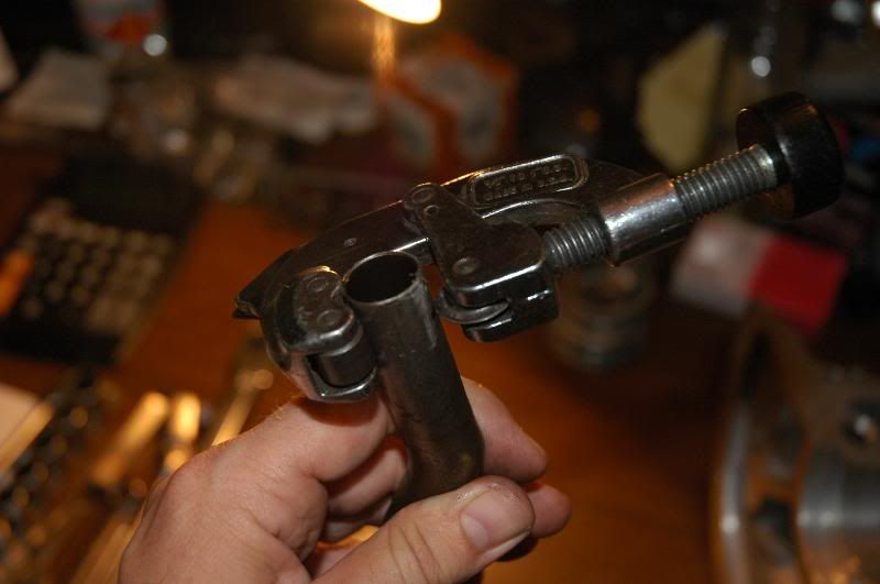
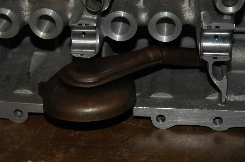
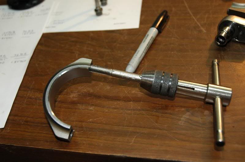
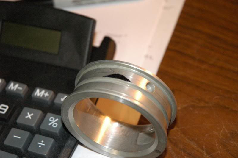
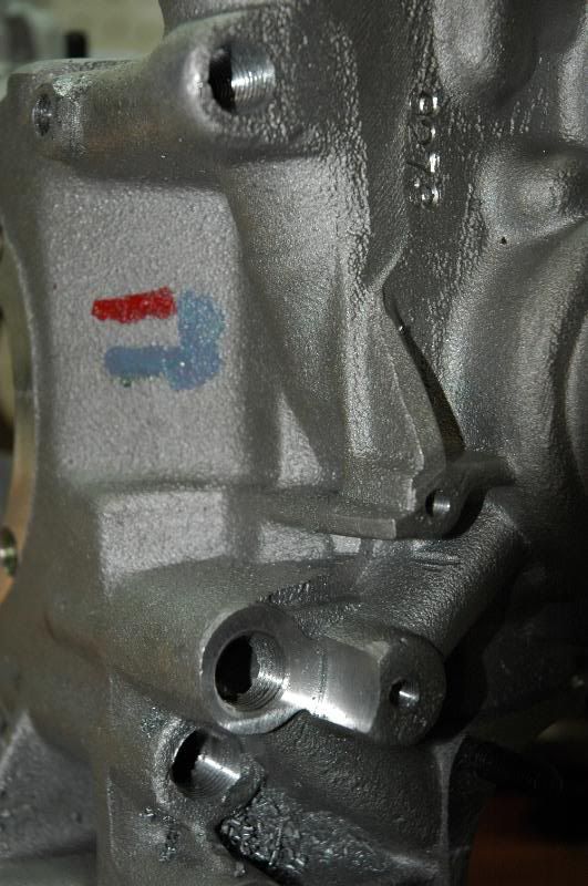
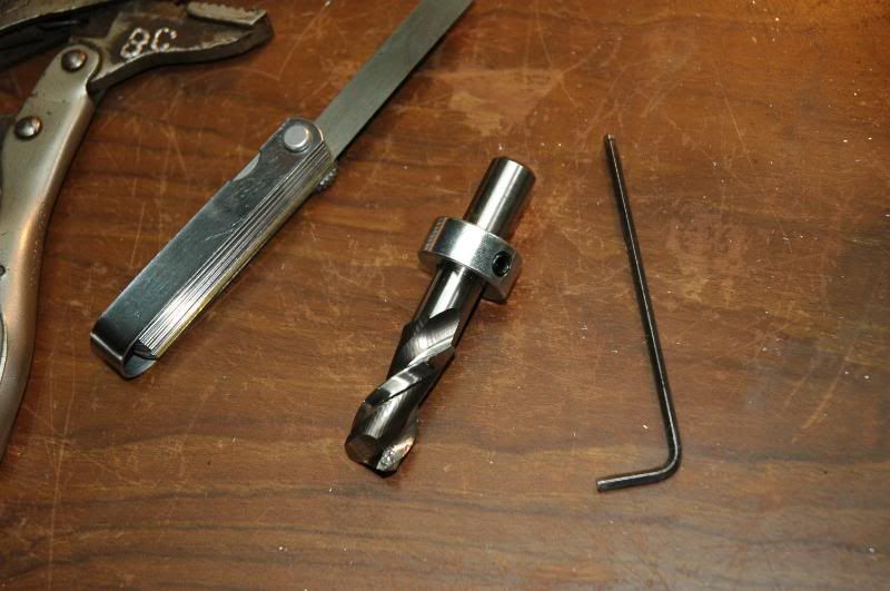
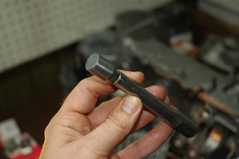
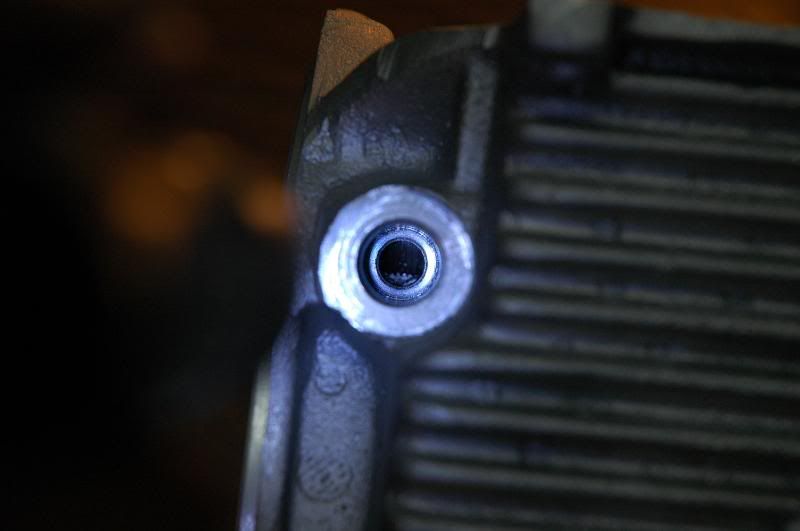
The next thing is a little detail I like to do that most people never think of, and that is making sure the oil pressure relief plunger has a nice surface to seal against. If the plunger does not form a good seal oil and hence pressure will leak past it and your oil pressure will not be as good as it should. Aircooled.net sells a tool for cleaning up this surface and it works quite nicely.
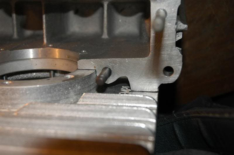
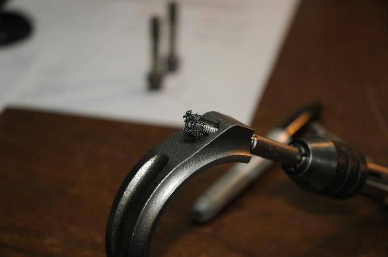
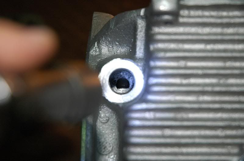
Here's what the surface looked like on my new case. It's hard to see, but there is a step around the edge of the surface that the plunger would have hit and formed a terrible seal against.
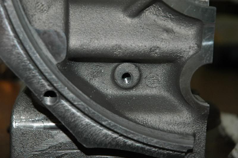
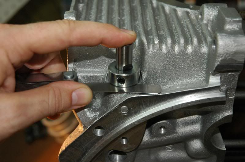
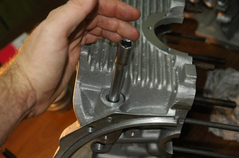
Loosen the collar on the tool, put it in the hole so it bottoms out, then put a .010" feeler gauge in as shown and lock down the collar...
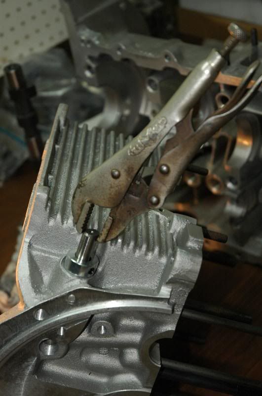
Turn the tool by hand with a pair of vise grips or what ever till you have taken off .010". Visually inspect the surface you just cut and repeat until you have a nice flat surface for the plunger to seat against. Keep track of how much material you removed, then shim your spring accordingly to achieve the proper pre-load on the spring
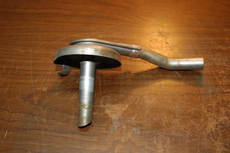
To really make the surface nice I glue a piece of sand paper to the top of a plunger then I lap the surface with it till it's nice and smooth...
That's all for now, but there is plenty more where that came from. I have photos of about every step and will continue the writeup later...