How-To: Front Suspension Beam Narrowing
This article is applicable to a king & link-pin beam, but some of the stages are similar to those required for a ball-joint beam. The inner wings on this particular car (a '56 Oval) will not be modified in any way to clear the shock towers. Therefore the inner section of the tower will be removed, allowing the beam to be narrowed by maximum of 20mm each side. This will leave 1-2mm clearance between the tower and the inner wing.
When the beam is stripped down, make sure the torsion bars are labelled for top and bottom and which way round they go.
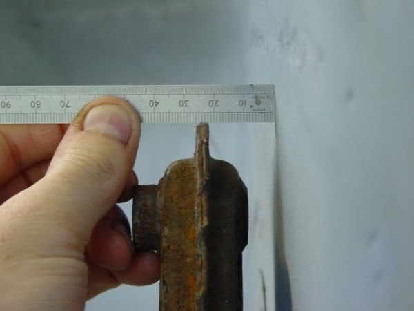
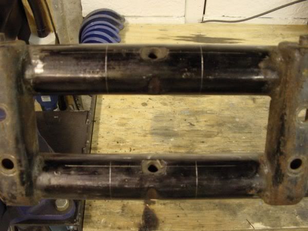
This car will be fitted with CB Performance 2.5" dropped spindles and the obligatory Sway-a-Way adjusters. Start by marking out the beam by scribing a horizontal and vertical centreline through each original torsion bar pinch screw hole. Now mark two vertical lines around the tubes 45mm each side of the centreline, these are the cut lines. A total of 90mm will be removed from the centre, this is made up of 50mm for the adjuster and 20mm + 20mm narrowing.
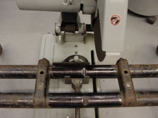
Now cut the beam inside of all four cut lines. This is ideally achieved in a cut-off saw or bandsaw for accuracy, but hacksawing against a worm-drive hose clip is just as good. Ensure the cuts are square and accurate. You will then end up with the beam in two separate pieces.
Before assembly, chamfer the ends of the beam tubes and the adjusters to allow for weld penetration. Follow the instructions supplied with your adjusters for positioning them relative to ride height adjustment. Here I set them for the full 4" drop, so set the original horizontal scribe line through the centre of the top of the adjuster slot. To align everything straight and square, clamp each tube to a piece of 50mm x 50mm angle iron. Tack weld the adjusters in position.
Now fully weld around the adjusters, try to keep the angle iron clamped to the tubes for as much of the weld as possible to prevent bending. Some of the welds will however have to be carried out without the angle irons.
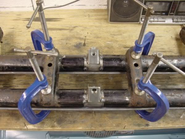
The uprights will now need to be re-positioned, grind the welds out that attach the uprights to the tubes, there are usually eight stitch welds on each upright. Final removal is aided with a large hammer! Clean up the remains of the original welds, and position the uprights about the centre of the beam with the hole centres at 290mm. Clamp the uprights in place and re-stitch weld as before.
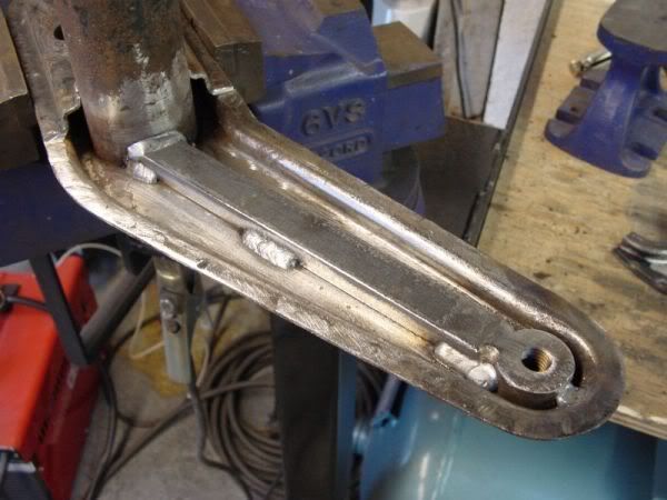
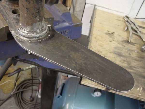
Now for the modification to the shock towers. In the picture below you can see the inner secton of the shock tower removed, this is achieved by grinding through all the spot welds. The top shock mounting boss was also removed and discarded, a new boss was machined from 30mm dia steel bar. The new boss was tack welded in from behind. To impart some of the lossed rigidity by removing the inner shock tower, a piece of 20mm x 10mm x 180mm long flat bar was stitch welded in place.
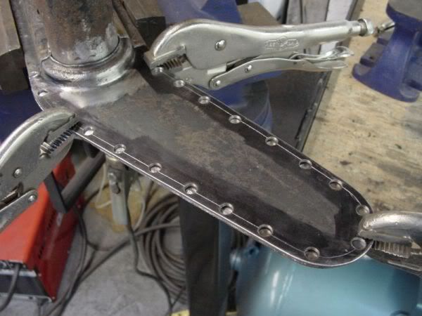
A new inner shock tower plate was cut from 2mm steel sheet using a cardboard template. Though not essential, I chose to finish the area where this plate meets the top tube to a 'factory look' by using an old bottom section from a scrap beam.
This new plate is drilled for plug-welding with a series of 7mm holes.
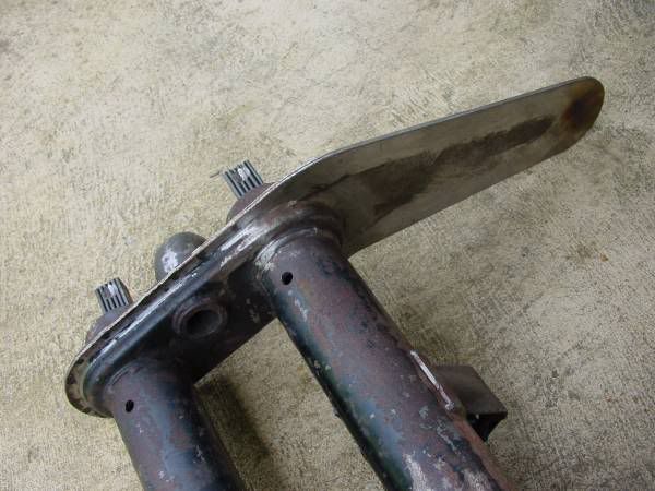
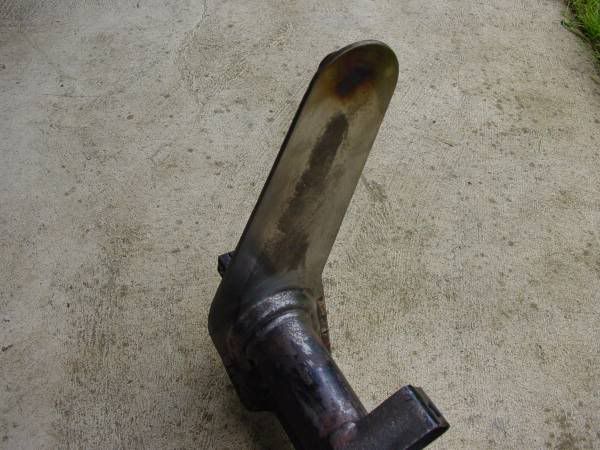
The finished shock tower as VW would have made them!
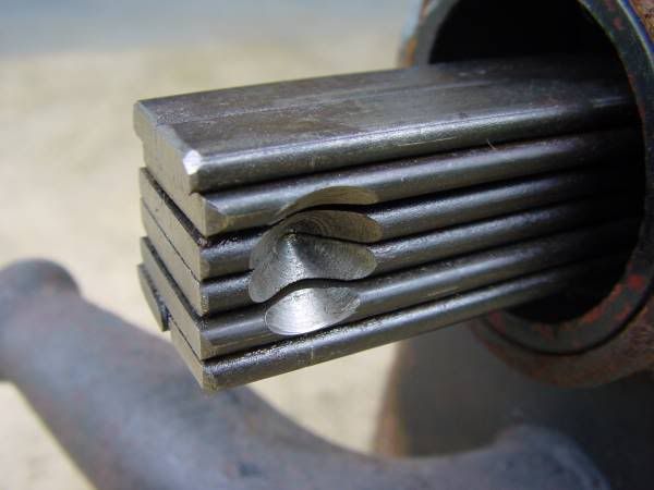
The torsion bars must now be shortened. Measure 20mm from each end and scribe a cutting line. Before cutting the bar, also measure 20mm from the centre of the original pinch screw dimple and scribe a new centre line. Before drilling, prepare a 12mm drill by grinding the point to 90deg. Clamp the torsion bar leaves either with Mole grips or in a drilling vice. Firstly drill a 5mm pilot hole to about 5mm deep, then drill the new 12mm dimple hole slowly and with plenty of coolant/lubricant. Just match the original hole for depth.
The torsion bars can now be cut down. This should ideally be carried out in a cut-off saw, but careful use of a cutting disc in an angle grinder or even a hacksaw will achieve the same result. Be careful not to get the ends too hot. Chamfer the ends of the bars slightly with an angle grinder to aid insertion into the Sway-a-Way adjusters.
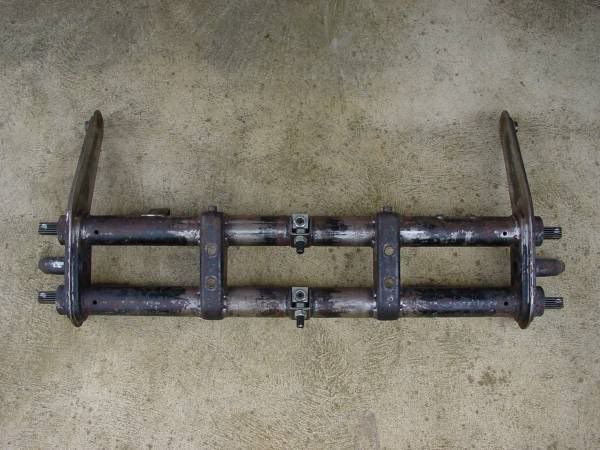
The finished beam assembled with torsion bars ready for trial fitting on the car, prior to being stripped for painting or powder coating.